The implementation of filters with digital circuits having finite word-length introduces unavoidable quantization errors. These effects have been widely studied [1–7]. The three common sources of quantization error are: input quantization, coefficient quantization and quantization in arithmetic operations. In [2–4, 6] papers the statistical characteristics of the quantization errors of scalar signals have been studied. The influence of all three sources of quantization errors on performance of a Chebyshev digital third-order highpass filter was investigated in [5] also for the scalar input signals. The quantization errors of complex input signals, which were represented by its inphase and quadrature components were studied in [7] to evaluate the performance of coder/decoders with phase shift keying. However, only computer simulation results were presented in this paper.
Usually digital signal processing of narrowband radio signals (i.e. signals for which inequality  is valid) is carried out after the demodulation of the input signal into the quadrature components. Hence, our attention in this paper will be on input quantization of the complex signals. We adopt stochastic methods to analyse quantization errors [1–6]. The block diagram of the input narrowband signals converter, which produces the quadrature components of the signals and then transforms them into digital form is shown in fig. 1 (the left part of the plot). is valid) is carried out after the demodulation of the input signal into the quadrature components. Hence, our attention in this paper will be on input quantization of the complex signals. We adopt stochastic methods to analyse quantization errors [1–6]. The block diagram of the input narrowband signals converter, which produces the quadrature components of the signals and then transforms them into digital form is shown in fig. 1 (the left part of the plot).
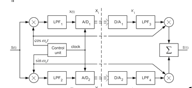
Fig. 1. Block diagram of narrowband signals' converter
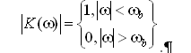
The converter contains two frequency mixtures, two low pass filters (LPF), two analog-to-digital converters (A/D) and a control unit. The quantizing (roundoff) errors of the inphase Xi and the quadrature Yi components are caused by limited bit representation of the code words of these components. To quantitatively evaluate these errors we will transform the quadrature components which have the roundoff errors into the narrowband signal again, and then we will estimate the amplitude and phase errors in this signal in comparison with the input one. For this purpose we will add in the block-diagram in fig. 1 the necessary blocks (the right part of the plot): digital-to-analogue converters (D/A), low pass filters (LPF) which restore the continuous analogue signal, frequency mixtures and adder. Assume all blocks work in ideal mode, don't introduce the delay, then the magnitude of the transfer function of the LPF is
If the Nyquist constraint is valid the values of the restored analogue quadrature components  and and  ( ( is the clock period) will be equal to the discrete values of quadrature components – is the clock period) will be equal to the discrete values of quadrature components – and and  respectively. respectively.
Preliminaries
Let  and and  be the inphase and quadrature components at the input of the A/D converters. At each sampling instant i, the quantized outputs and , the quantization (roundoff) errors be the inphase and quadrature components at the input of the A/D converters. At each sampling instant i, the quantized outputs and , the quantization (roundoff) errors  and and  , and the input , and the input  and and  are related by are related by
 , ,  . (1) . (1)
Suppose roundoff errors are independent with zero mean, variance  and uniform distribution in interval and uniform distribution in interval  , cf. [6]. , cf. [6].  is the step of quantizing. is the step of quantizing.
If the input signal is a narrowband signal is a narrowband signal
 , ,
then the output signal  is also a narrowband signal and can be written in the form is also a narrowband signal and can be written in the form
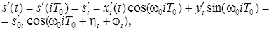 (2) (2)
where the values of and are given by formula (1).
The vector representation of the  and and  signals is given in fig. 2. Obviously, we have signals is given in fig. 2. Obviously, we have
 . (3) . (3)
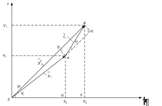
Fig. 2. Vector representation of input and output (distorted) signals
Under the assumption about independent random variables and the hypothesis about uniform distribution of the random angles  may be accepted. It is clear from the fig. 2 and formula (2) that the signal has a parathytic amplitude modulation as well as a phase modulation. The parathytic modulation is caused by the quantizing errors of the signal's quadrature components. may be accepted. It is clear from the fig. 2 and formula (2) that the signal has a parathytic amplitude modulation as well as a phase modulation. The parathytic modulation is caused by the quantizing errors of the signal's quadrature components.
Amplitude error analysis of the quantized narrowband signals.
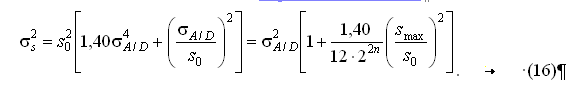
The variance of the magnitude  is is
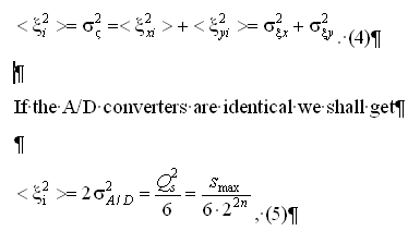
where smax is the maximum available amplitude of the input signals of the A/D converter, n
– is the number of bits of the A/D converter.
It is interesting to note that quantizing errors exist only when the input signals exists, nevertheless these errors are additive but not multiplicative because the values of these errors depend on the quantizing step , but do not depend on the amplitude of the input signal . (See formula (5)). We are interested in the amplitude and phase of the output signal . Let us find the statistical characteristics of the amplitude and phase.
The length  of the vector of the vector  can easily be found from the triangle OAB (see fig. 2) can easily be found from the triangle OAB (see fig. 2)
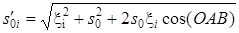 , (6) , (6)
where  . .
As the amplitude  is the random variable, let us find the mean of this amplitude is the random variable, let us find the mean of this amplitude
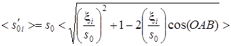 .(7) .(7)
Since for many practical interesting cases  , we shall use the decomposition , we shall use the decomposition  , hence , hence
 . (8) . (8)
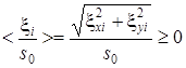
Considering the formulas (4) and (5) we will find the mean of values in formula (8)
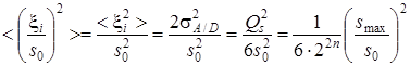 , (9) , (9)
 . (10) . (10)
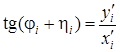
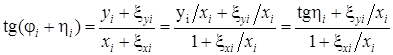
The angle  is (see fig. 2) is (see fig. 2)
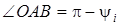 , hence , hence
 , (11) , (11)
because is a random variable with uniform distribution in interval  . .
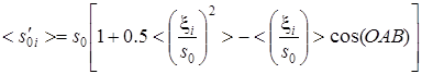
By inserting the values given by formulas (9)–(11) into the formula (8) we get the mean of the amplitude
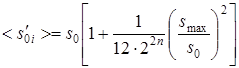 .(12) .(12)
Notice that the value of s0
in the formula (12) has to satisfy
 (12a) (12a)
as the amplitude of the input signal must exceed the quantization step.
Analysis of formula (12) shows that if  and if the number of bits of the A/D converter and if the number of bits of the A/D converter  then the mean then the mean  is equal to the is equal to the  with the error less than 0,5 %. This means that the mean amplitude of output signal is practically equal to the amplitude of the input signal. with the error less than 0,5 %. This means that the mean amplitude of output signal is practically equal to the amplitude of the input signal.
The variance of amplitude can be found considering formula (6) and the fact, that 
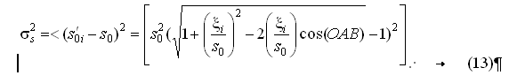
Supposing that and using the decomposition , the formula (13) can be written
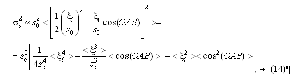
Where
 . .
If we have identical A/D converters, then
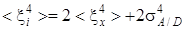 , (15) , (15)
Where
 . .
Finally we get, considering formula (11) and the fact that
Under the constraint given by formula (12') we get
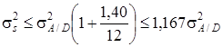 . .
The last expression means that the variance of the amplitude error of the signal caused by quantization errors of its quadrature components is practically equal to the variance of the quantization error of the A/D converter.
Phase error analysis of the quantized narrowband signals
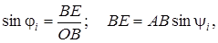
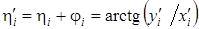
The phase error  i
of the distorted signal (we measure the phase error by comparing the input phase with the output phase) can be found from fig. 2. Actually, from the triangle OBE we get i
of the distorted signal (we measure the phase error by comparing the input phase with the output phase) can be found from fig. 2. Actually, from the triangle OBE we get
 hence hence
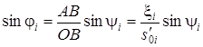 .(17) .(17)
Let us define the limits of the angle  variation. From the triangle OBF we get variation. From the triangle OBF we get
 , (18) , (18)
and from the triangle OAG we get
 . (19) . (19)
Transforming formula (18) considering the formula (19) we obtain
 . (20) . (20)
It is obvious from formula (20) what the maximum phase error  will be, provided the value of the inphase component is minimum and the quantization error is maximum, i.e. provided will be, provided the value of the inphase component is minimum and the quantization error is maximum, i.e. provided
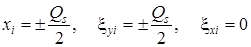 . (21) . (21)
Inserting these values into formula (20), we get
 . (22) . (22)
Transforming in the formula (22) the sum of angles [8] we get
 . (23) . (23)
Solving the equation (23) with respect to  we get we get
 . (24) . (24)
It is clear that maximum value of the angle will be, if  , hence , hence
 .(25) .(25)
We have found that maximum phase error does not exceed 53°. Therefore we can replace sin in the formula (17) by its argument (with the error less than 10 %)
 . (26) . (26)
The mean of the phase error is
 , (27) , (27)
where  . .
The variance of the phase error can be found from formulas (6) and (9)
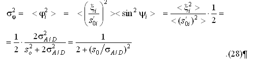
Inserting the value of  , given by formula (5) into formula (28), we finally get the phase variance , given by formula (5) into formula (28), we finally get the phase variance
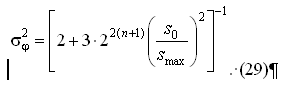
The maximum value of the phase variance will occur if the input signal has the minimum, given by formula (12')
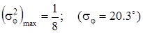 . .
Fig. 3 shows a plot of phase variance a against number of A/D converter bits for various values of ratio  (solid curves). The computation was carried out in accordance with formula (29). (solid curves). The computation was carried out in accordance with formula (29).
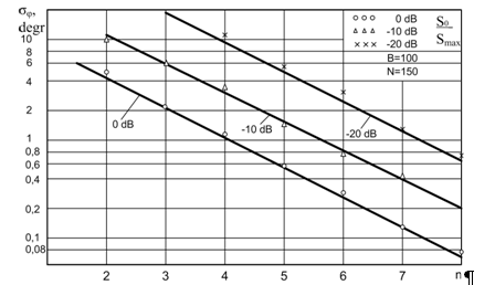
Fig. 3. Standard deviation of the phase quantization error for different rations as a function of code word length
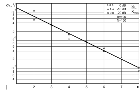
Fig. 4. Standard deviation of the amplitude quantization error as a function of code word length
Сomputer simulation of the roundoff errors of the quadrature components. The computer simulation of the quantizing errors of the quadrature components of the narrowband signal was carried out with the intention to check the validity of the obtained formulas (16) and (29).
The LFM signal with time-compression ratio 100 was chosen as a narrowband signal. Quantization of the inphase and quadrature components was made in accordance with formulas
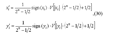
where 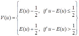 – operator of quantization. – operator of quantization.
 is an integer part of variable u, n is a number of A/D converter bits. is an integer part of variable u, n is a number of A/D converter bits.
For each sample of the input signal the quantizing values of inphase and quadrature components were defined and then amplitude and phase of the distorted signal were determined according to formulas
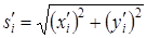 , ,  . (31) . (31)
At the same time the phase of the input signal was computed
 . .
The phase error was then founded as the difference between  and and  . These operations were made for 150 samples of the input signal. Then mean and variance of the amplitude error were defined as well as the same parameters of the phase error. The achieved results show that the mean of the amplitude is very close to the amplitude of the input signal (within 3 %), the mean of phase error is close to zero (in all cases the mean was less than ± 0,1 . These operations were made for 150 samples of the input signal. Then mean and variance of the amplitude error were defined as well as the same parameters of the phase error. The achieved results show that the mean of the amplitude is very close to the amplitude of the input signal (within 3 %), the mean of phase error is close to zero (in all cases the mean was less than ± 0,1 ). The plots of the phase standard deviation against the number of bits of the A/D converter are shown in fig. 3 for different rations s0/smax by points. The plots of the amplitude standard deviation against number of bits n are shown in fig. The coincidence between theoretical and simulation results are rather good, which shows the validity of our assumptions. ). The plots of the phase standard deviation against the number of bits of the A/D converter are shown in fig. 3 for different rations s0/smax by points. The plots of the amplitude standard deviation against number of bits n are shown in fig. The coincidence between theoretical and simulation results are rather good, which shows the validity of our assumptions.
Probability distribution laws of the amplitude and phase errors have also been evaluated by the means of computer simulation. For this purpose a LFM signal with time-compression ratio 6 400 was used. Statistical distributions were estimated with usage of 9 600 samples for inphase and 9 600 samples for quadrature components. Thirteen points of these statistical distributions were chosen. The plot of the statistical distribution law  of the phase error values is shown in fig. 5 for various numbers of the A/D converters bits. fig. 6 shows the amplitude error distribution of the phase error values is shown in fig. 5 for various numbers of the A/D converters bits. fig. 6 shows the amplitude error distribution  computed for the same case computed for the same case
.

Fig. 5. Probability distribution laws of the phase error for different word length, 

Fig. 6. Probability distribution laws of the amplitude error for different word-length, 
Conclusion
narrowband signal error
The results of theoretical analysis and computer simulation of the amplitude and phase errors of the narrowband signal, caused by quantizing of the signal's inphase and quadrature components show that the mean of the amplitude of the distorted signals remains equal to the input amplitude, but the output amplitude becomes fluctuated with the variance, determined by the variance of D/A converter error. The phase error has zero mean, maximum deviation 53° and a variance which is inversely proportional to the number of quantization levels. The results achieved may be used in digital filters' design.
r
eferences
1. Rabiner, L.R. Theory and Application of Digital Signal Processing / L.R. Rabiner, В. Gold // Englewood Cliffs, NJ. – Prentice-Hall, 2008.
2. Агеев, Р.В. Логарифмическая дискретизация сигналов с заданной абсолютной погрешностью / Р.В. Агеев, Ю.Н. Овчаров // Автометрия. – 2008. – № 6. – С. 23–27.
3. Лифшиц, Н.А.Численные характеристики ошибок квантования амплитуды / Н.А. Лифшиц, В.Е. Фарбер // Автоматика и телемеханика. – 2008. – т. 39, № 12. – с. 176–179.
4. Домрачеев, В.Г. Критерий оценки точности цифровых преобразователей угла / В.Г. Домрачеев, Б.С. Мейко // Измерительная техника. – 2008. – т. 18, № 11. – С. 22–25.
5. Koffler, H. Quantization and roundoff errors in a digital MTI filter, Siemens Forsch. and Entwicklungsber / H. Koffler. – Germany, 2010 – Vol. 2, № 2. – p. 73–78.
6. Snipad, A.B. A necessary and sufficient condition for quantization errors to be uniform and white / A.B. Snipad, D.L. Snyder // IEEE Trans, on Acoust. Speech and Sign. Proc.Vol. – ASSP-25. – 2007. – № 5 (Oct.)–p. 442–448.
7. O'Neal, Iz. Digital encoding of phase shift keying voiceband data signals / Iz. O 'Neal, R.R. Koneru, I.P. Agrawal // Conf. record of Int. Conf. on Acoustics Speech and Signal processing, ICASSP-80. Denver. Co. – 2010. – April 9–11. – P. 315–318.
8. Dvite, G.B. Tables of Integrals and Other Mathematical Data / G.B. Dvite // The Mac Millan Company. – N.Y., 2011. – 634 p.
|